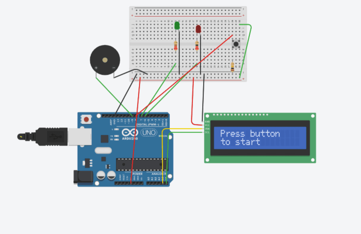
Using Tinkercad, I created an early design card to visualize how the timer should function from the user’s perspective. This included mapping out the study and break durations, button interactions, and the alert system. Building this digital mockup in Tinkercad helped me clarify the user flow and understand the overall structure of the device before moving on to wiring the circuit or writing the C++ logic.
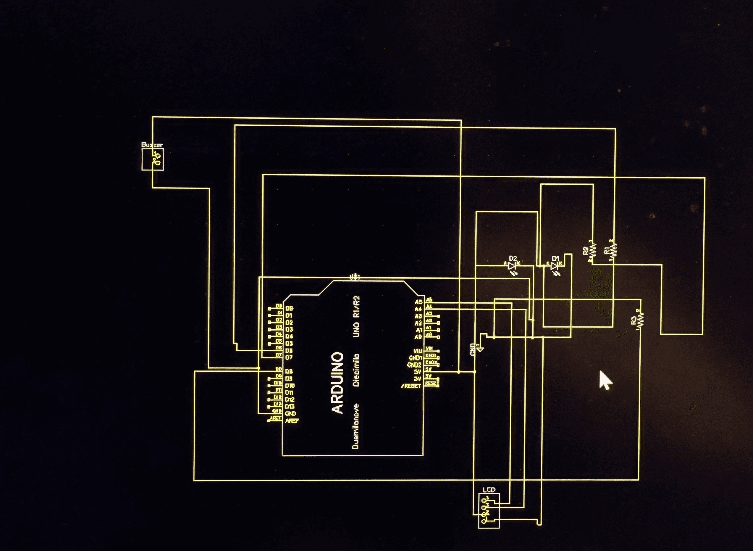
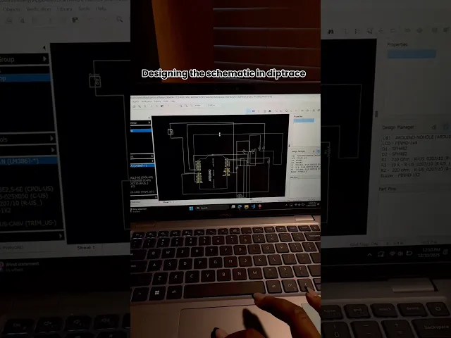
SCHENATIC & PCB layout.
After completing the schematic, we moved on to designing the PCB layout. This step involved arranging each component, LCD header pins, LEDs, buzzer, resistors, and the button onto a board in a way that was organized, efficient, and ready for manufacturing. We planned the traces, adjusted clearances, and positioned components to make the board easy to assemble and troubleshoot. Working together on the layout helped us understand how real circuits transition from digital design to a physical PCB, and ensured that our final board would be clean, functional, and safe to solder.
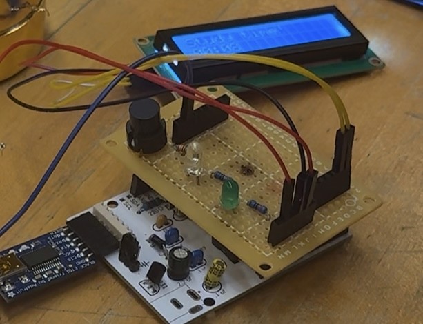
Soldering & Final Assembly
After completing the PCB layout, our team soldered all the components onto the protoboard, following the schematic and trace design. We carefully secured the LCD header pins, LEDs, buzzer, resistors, and button, checking each joint to avoid shorts or loose connections. Once soldering was complete, we assembled the full device, tested the timing cycles, and confirmed that the alerts and display were working as expected. This step turned our digital design into a fully functioning physical product.
Problems & Challenges
Throughout the project, we faced challenges that required quick iteration and collaboration. We struggled with how to organize the interface on the LCD, how to make our alerts intuitive, and how to coordinate as a team during debugging. These obstacles prompted us to refine our user flow, enhance communication, and test more intentionally, enabling us to better understand the balance between usability and technical constraints.
Room for Improvement
If we continued developing this timer, we would focus on improving usability and overall product experience. This includes creating a cleaner enclosure, adding adjustable study/break times, improving the LCD layout, supporting battery power, and offering customizable alert tones. These enhancements would make the device more user-friendly, accessible, and practical for everyday use.
Lessons Learned
This project strengthened my skills in both engineering and user-centered design. I learned how to translate ideas into functional hardware through schematics, PCB layouts, and iterative prototyping, while also grounding each decision in user needs and clarity of interaction. Early testing and debugging improved my technical problem-solving skills, and strong communication helped me collaborate effectively with my teammate throughout each stage. Overall, I gained experience merging engineering thinking with product design to move from concept to a working device.
DEMO
The final demo video walks through the entire process, featuring me as I assemble, test, and operate the Pomodoro Timer. It shows each major stage, from wiring and soldering to programming and final adjustments.
SCHENATIC & PCB layout.
After completing the schematic, we moved on to designing the PCB layout. This step involved arranging each component, LCD header pins, LEDs, buzzer, resistors, and the button onto a board in a way that was organized, efficient, and ready for manufacturing. We planned the traces, adjusted clearances, and positioned components to make the board easy to assemble and troubleshoot. Working together on the layout helped us understand how real circuits transition from digital design to a physical PCB, and ensured that our final board would be clean, functional, and safe to solder.
Soldering & Final Assembly
After completing the PCB layout, our team soldered all the components onto the protoboard, following the schematic and trace design. We carefully secured the LCD header pins, LEDs, buzzer, resistors, and button, checking each joint to avoid shorts or loose connections. Once soldering was complete, we assembled the full device, tested the timing cycles, and confirmed that the alerts and display were working as expected. This step turned our digital design into a fully functioning physical product.
Problems & Challenges
Throughout the project, we faced challenges that required quick iteration and collaboration. We struggled with how to organize the interface on the LCD, how to make our alerts intuitive, and how to coordinate as a team during debugging. These obstacles prompted us to refine our user flow, enhance communication, and test more intentionally, enabling us to better understand the balance between usability and technical constraints.
Room for Improvement
If we continued developing this timer, we would focus on improving usability and overall product experience. This includes creating a cleaner enclosure, adding adjustable study/break times, improving the LCD layout, supporting battery power, and offering customizable alert tones. These enhancements would make the device more user-friendly, accessible, and practical for everyday use.
Lessons Learned
This project strengthened my skills in both engineering and user-centered design. I learned how to translate ideas into functional hardware through schematics, PCB layouts, and iterative prototyping, while also grounding each decision in user needs and clarity of interaction. Early testing and debugging improved my technical problem-solving skills, and strong communication helped me collaborate effectively with my teammate throughout each stage. Overall, I gained experience merging engineering thinking with product design to move from concept to a working device.
DEMO
The final demo video walks through the entire process, featuring me as I assemble, test, and operate the Pomodoro Timer. It shows each major stage, from wiring and soldering to programming and final adjustments.